I spent quite a lot of time trying to decide if I should convert the quill or the knee. Quite a few people have converted the knee with very good success and the required bracketry would have been a little simpler. I decided to go with the Quill anyway because I think the quill is designed for continuous, repeated up/down movement, whereas the knee is not. I realize, that for my purposes, the knee ways would still last far beyond whatever use I would put into the machine but it seemed technically incorrect. I may yet convert the knee as well...
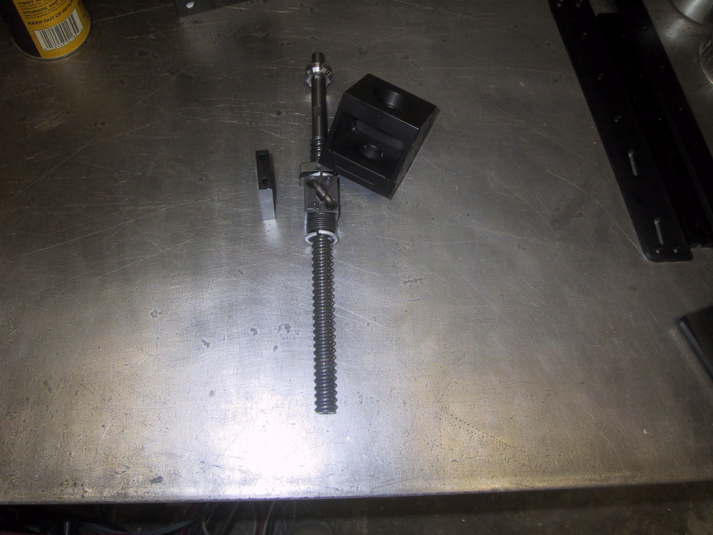
Of the three axis, the quill was certainly the most complicated. I designed the assembly around a 5/8" diameter ballscrew with a single ballnut with oversized balls, which should give me around 0.001-2" backlash in the quill. The motor I'm using for the quill is very wimpy - 60oz/in continuous / 300oz/in peak. I may have to replace the motor or add an additional belt reduction.
 |
Drawn up in CAD, it looks so simple! | 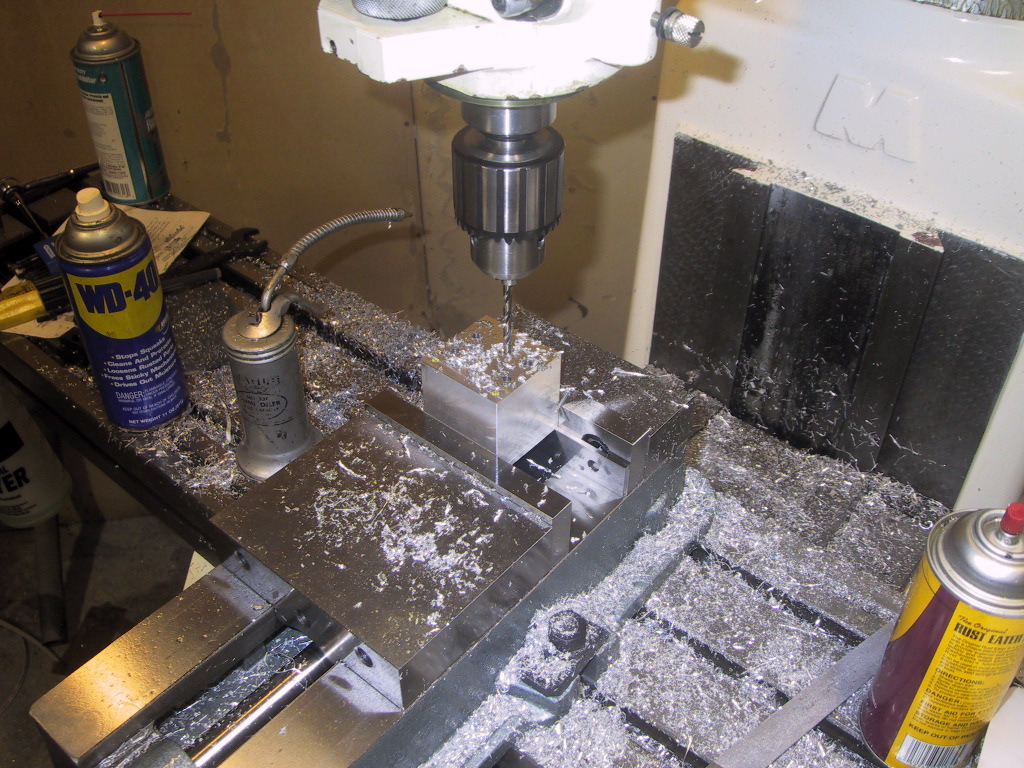 |
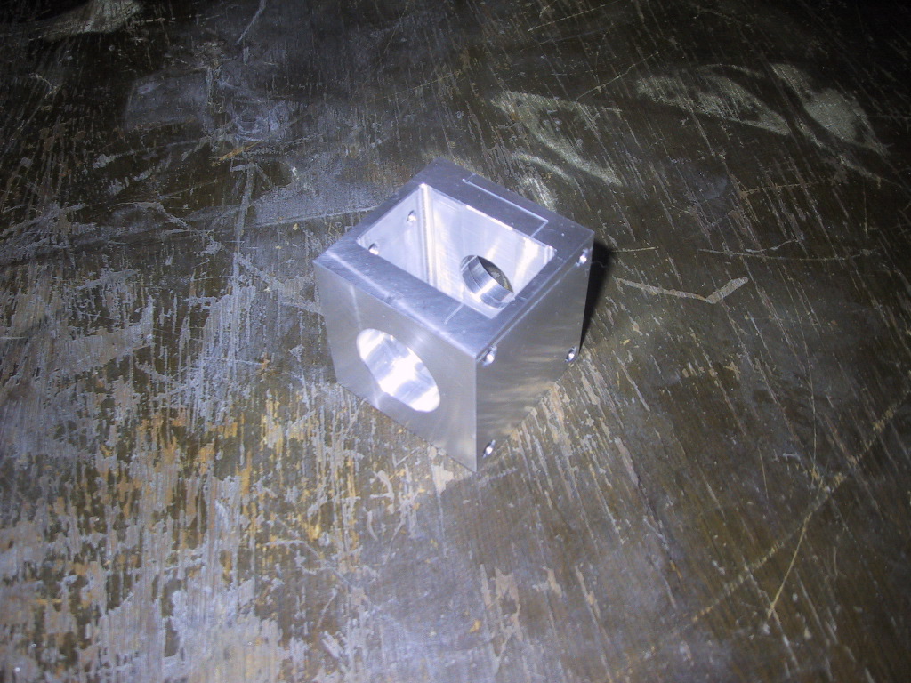
I made the main bearing block first. Unfortunately I didn't take any pictures of making the initial cube. It came out within +/- 0.001" on squareness, size and parellelism. |
 |
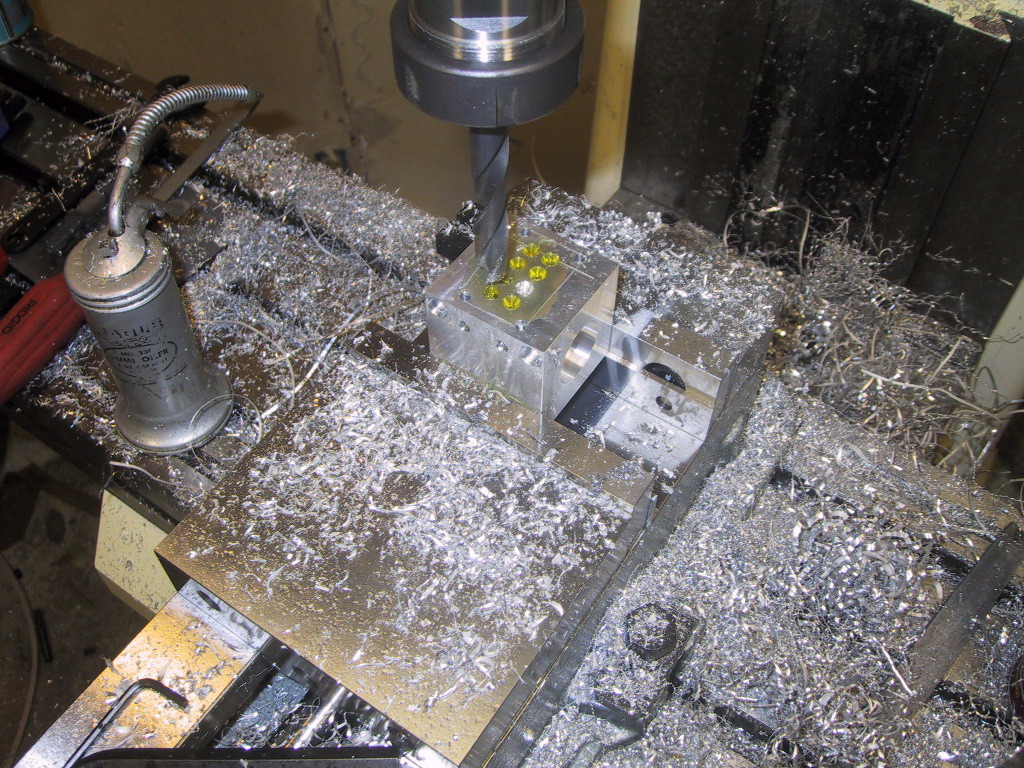
I drilled, tapped and counter-bored the font mounting holes. | 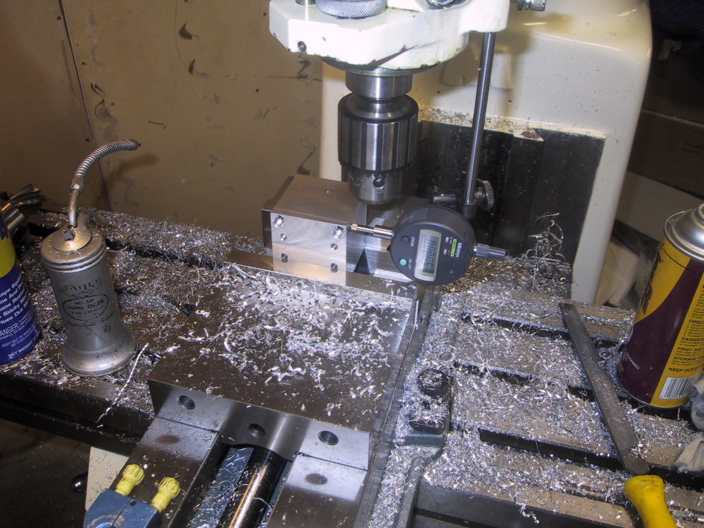 |
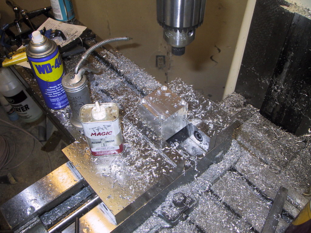
For making the bearing bores, I needed to make sure that they were square to everything else. So I checked the side and top for flatness with an indicator. |
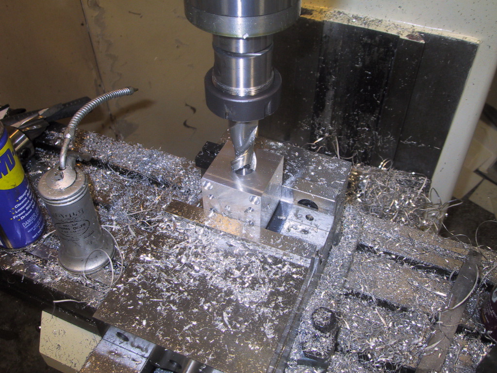 |
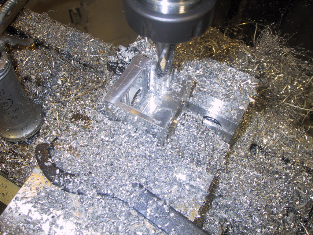
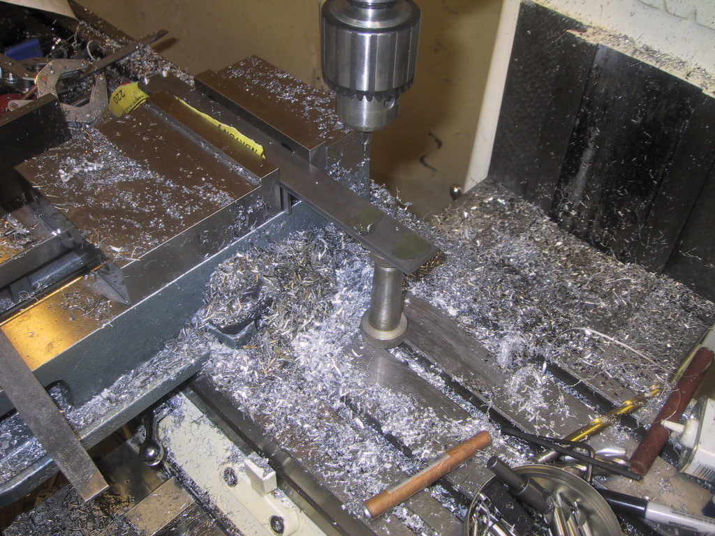
I drilled out the center hole (non-precision) with a drill and then finished it with an endmill. I then roughed out the bearing bore with 0.040", also with an endmill. |  |
I then turned it over, indicated to center and did the same thing on the other side. I do the final boring after I mill out the inside pocket. |
 |
Because I was very tired when I began to mill out the inside pocket, I started by tracing the outside of the pocket with a center drill at about 2-thou depth. I'm glad I did because I started to make the pocket 90 degrees out of where I wanted it! | 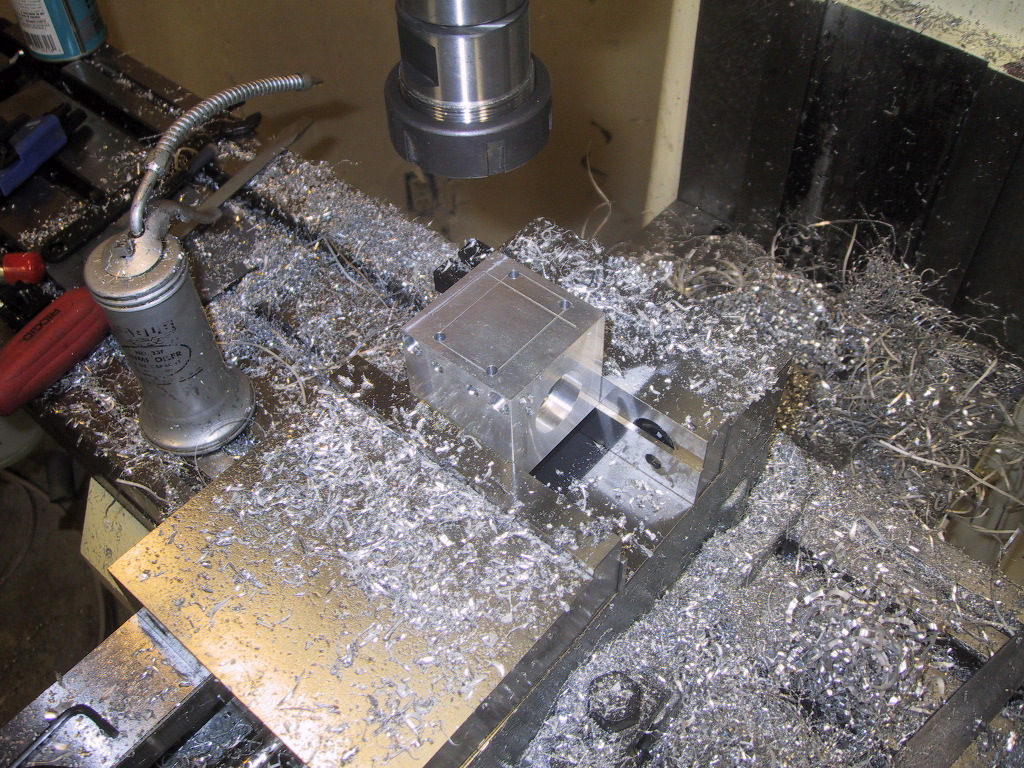 |
After I made the outline, I drilled a 3/16" hole in each corner. |
 |
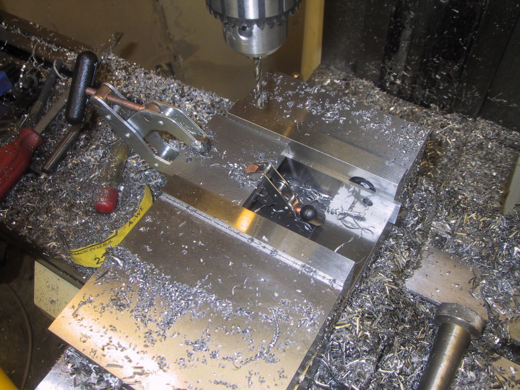
I then drilled several 5/8" holes to remove most of the material from the inside. The holes only go to 1/2" less than desired depth. |  |
Pretty ugly at this point! |
 |
I roughed it out with a 1/2" end mill - the bottom is now flat and within 1/8" of proper depth. | 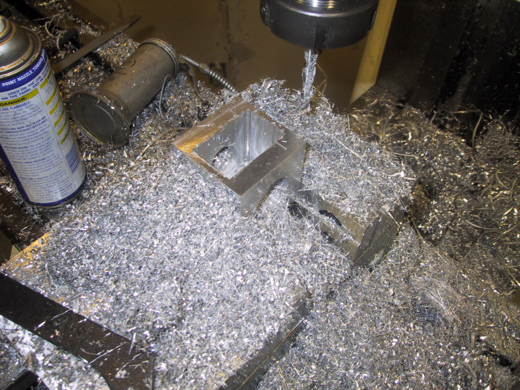 |
I cleaned it up with a very long 3/8" end mill - the 3/16" holes in the corner give a tighter corner radius that I could have gotten with the end mill. |
 |
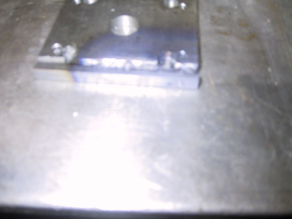
After I made the pocket, I did the final bore on the bearing pockets - unfortunately I didn't take any pictures. I did the bearing bores in two steps just in case the dimensions of the cube changed at all as stresses were relieved in the pocketing. |  |
Final dimensions, except for the inside pocket, which had looser tolerances, are all within 0.001" or less of my original specs. |
 |
I made the two side plates out of steel - I had to mill them to size, from 1.5" stock down to 1.25". Otherwise these were very straightforward - just a few holes in each. | 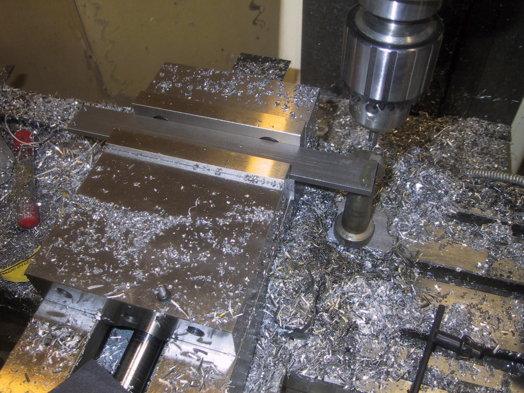 |
|
 |
Next I did the motor mount plates. I actually had to do them twice because the first set I drilled the holes 90 degrees to the direction they were supposed to be. | 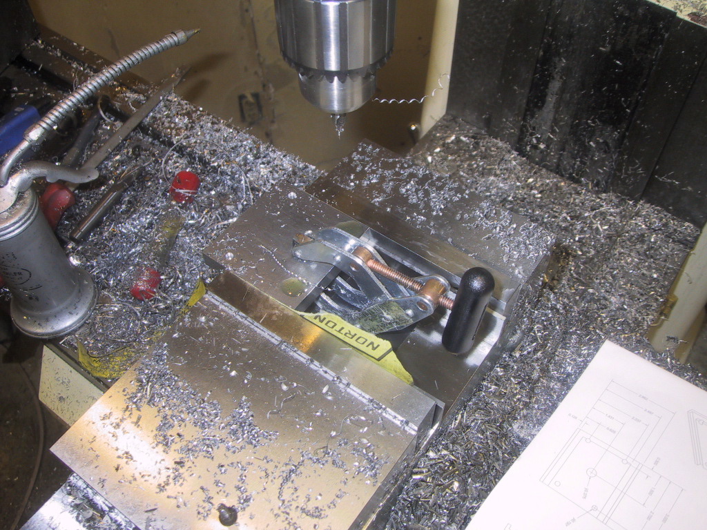 |
The sandpaper helps hold the two separate pieces in the vise. Although the Kant-Twist probably helps more! |
 |
Because I don't listen, I milled the slots with an end mill in a drill chuck. The drill chuck came off the taper and I ended up milling a very slanted slot that was about 1/8" deeper than I needed. | 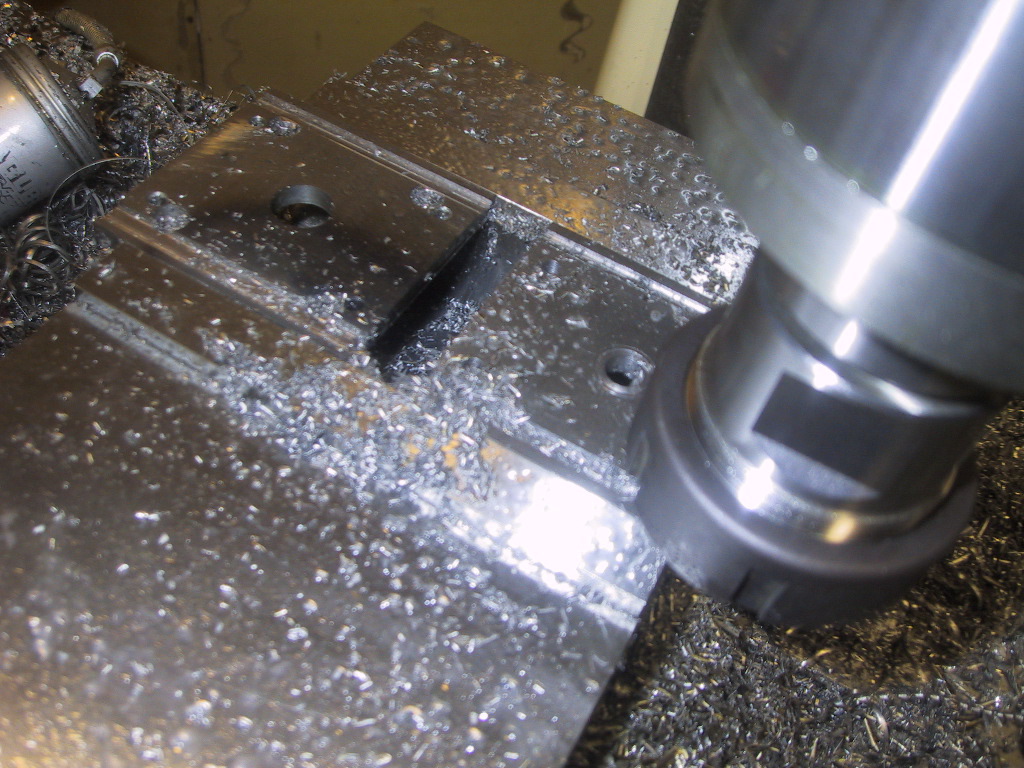 |
Luckily I have a welder! I filled in the too deep pass with filler rod and then re-did the slots. |
 |
Unless you look closely at the edges, you can't even tell it was filled. |  |
Next I did the main mounting plate. |
 |
All of the pieces for the Quill complete. I sent the steel pieces out for plating and the aluminum pieces for anodizing. | ||
 |
I'm still waiting for the steel parts to come back from the plater but the anodized parts came out really nice. | 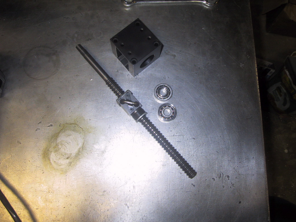 |
I'm waiting for the timing belt so I can assemble the bearings, shaft and pulley. |
Also see: CNC Conversion, Pt 1, CNC Conversion, Pt 3